 The diffraction pattern (Airy disc) of a red laser beam projected onto a plate after passing through a small circular aperture in another plate
Diffraction is the deviation of waves from straight-line propagation without any change in their energy due to an obstacle or through an aperture. Diffraction is the same physical effect as interference, but interference is typically applied to superposition of a few waves and the term diffraction is used when many waves are superposed.[1]: 433 The term diffraction pattern is used to refer to an image or map of the different directions of the waves after they have been diffracted.
Italian scientist Francesco Maria Grimaldi coined the word diffraction and was the first to record accurate observations of the phenomenon in 1660.
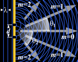
 Infinitely many points (three shown) along length project phase contributions from the wavefront, producing a continuously varying intensity on the registering plate


In classical physics, the diffraction phenomenon is described by the Huygens–Fresnel principle that treats each point in a propagating wavefront as a collection of individual spherical wavelets.[2] The characteristic pattern is most pronounced when a wave from a coherent source (such as a laser) encounters a slit/aperture as shown in the inserted image. This is due to the addition, or interference, of different points on the wavefront (or, equivalently, each wavelet) that travel by paths of different lengths to the registering surface. If there are multiple closely spaced openings, a complex pattern of varying intensity can result. Other types of apertures or obstacles lead to different patterns, some of which are described later on this page.
These effects also occur when a light wave travels through a medium with a varying refractive index, or when a sound wave travels through a medium with varying acoustic impedance – all waves diffract,[3] including gravitational waves,[4] water waves, and other electromagnetic waves such as X-rays, radio waves as well as matter waves.
Mathematically, diffraction is explained by solving the wave equation for electromagnetic waves, or Schroedinger's equation for matter waves, in some cases with relativistic corrections.
History
[edit] Thomas Young's sketch of two-slit diffraction for water ripple tank from his 1807 Lectures[5]: 139
The effects of diffraction of light were first carefully observed and characterized by Francesco Maria Grimaldi, who also coined the term diffraction, from the Latin diffringere, 'to break into pieces', referring to light breaking up into different directions.[6] The results of Grimaldi's observations were published posthumously in 1665.[7][8] Isaac Newton studied these effects and attributed them to inflexion of light rays. James Gregory (1638–1675) observed the diffraction patterns caused by a bird feather, which was effectively the first diffraction grating to be discovered.[9]
Thomas Young developed the first wave treatment of diffraction in 1800. In his model Young proposed that the fringes observed behind an illuminated sharp edge arose from interference between the direct transmitted plane wave and a cylindrical wave that appears to emitted from the edge.[10]: 57
Augustin-Jean Fresnel revisited the problem and devised an alternative wave theory based on Huygens' principle. In this model, point sources of light are distributed up to the diffraction edge but not in the barrier. These point sources are driven by the incoming plane wave and they interfere beyond the barrier. Fresnel developed a mathematical treatment from his approach and Young's model was initially considered incorrect. Later work showed that Young's more physical approach is equivalent to Fresnel mathematical one.[10]: 58
In 1818, supporters of the corpuscular theory of light proposed that the Paris Academy prize question address diffraction, expecting to see the wave theory defeated. When Fresnel's presentation on his new theory based on wave propagation looked like it might take the prize, Siméon Denis Poisson challenged the Fresnel theory by showing that it predicted light in the shadow behind a circular obstruction. Dominique-François-Jean Arago proceeded to demonstrate experimentally that such light is visible, confirming Fresnel's diffraction model.[11]: xxiii [12]
In 1859 Hermann von Helmholtz and later in 1882 Gustav Kirchhoff developed integral equations for diffraction based on the concepts proposed by Fresnel as well as approximations needed to apply them. In general all these approaches require formulating the problem in terms of virtual sources. Cases like absorbing barrier require methods developed in the 1940s based on transverse amplitude diffusion.[10]: 58
Mechanism
[edit] Single-slit diffraction in a circular ripple tank
In classical physics, diffraction arises because of how waves propagate; this is described by the Huygens–Fresnel principle and the principle of superposition of waves. The propagation of a wave can be visualized by considering every point on a wavefront as a source for a secondary spherical wave. The wave displacement at any subsequent point is the sum of these secondary waves. It is possible to obtain a qualitative understanding of many diffraction phenomena by considering how the relative phases of the individual secondary wave sources vary, and, in particular, the conditions in which the phase difference equals half a cycle in which case waves will cancel one another out. When waves are added together, their sum is determined by the relative phases as well as the amplitudes of the individual waves so that the summed amplitude of the waves can have any value between zero and the sum of the individual amplitudes. Hence, diffraction patterns usually have a series of maxima and minima.[citation needed]
In quantum mechanics, diffraction is also described in terms of a wave, but the wavefunction represents a probability amplitude whose modulus squared is the probability of detection. The light and dark regions in diffraction patterns are then areas where the quanta are more or less likely to be detected.[13]
Quantitative models which allow the diffraction to be calculated include the Kirchhoff diffraction equation (derived from the wave equation),[14] the Fraunhofer diffraction approximation of the Kirchhoff equation (applicable to the far field),[11]: 427 and the Fresnel diffraction approximation (applicable to the near field).[11] Most configurations cannot be solved analytically, but can yield numerical solutions through finite element and boundary element methods. In many cases it is assumed that there is only one scattering event, what is called kinematical diffraction, with an Ewald's sphere construction used to represent that there is no change in energy during the diffraction process.[15] For matter waves a similar but slightly different approach is used based upon a relativistically corrected form of the Schrödinger equation,[16] as first detailed by Hans Bethe.[17] The Fraunhofer and Fresnel limits exist for these as well, although they correspond more to approximations for the matter wave Green's function (propagator)[13] for the Schrödinger equation.[15][18] Multiple scattering models are required in many types of electron diffraction;[19] in some cases similar dynamical diffraction models are also used for X-rays.[20]
The simplest descriptions of diffraction are those in which the situation can be reduced to a two-dimensional problem. For water waves, this is already the case; water waves propagate only on the surface of the water.[21] For light, we can often neglect one direction if the diffracting object extends in that direction over a distance far greater than the wavelength. In the case of light shining through small circular holes, we have to take into account the full three-dimensional nature of the problem.
-
 Computer-generated intensity pattern formed on a screen by diffraction from a square aperture
 -
 Generation of an interference pattern from two-slit diffraction
 -
 Computational model of an interference pattern from two-slit diffraction
 -
 Optical diffraction pattern (laser, analogous to X-ray diffraction)
 -
![Colors seen in a spider web are partially due to diffraction, according to some analyses.[22]](//upload.wikimedia.org/wikipedia/commons/thumb/2/26/Diffraction_pattern_in_spiderweb.JPG/330px-Diffraction_pattern_in_spiderweb.JPG) Colors seen in a spider web are partially due to diffraction, according to some analyses.[22]
Colors seen in a spider web are partially due to diffraction, according to some analyses.[22]


,_(analogous_to_X-ray_crystallography).JPG)
![Colors seen in a spider web are partially due to diffraction, according to some analyses.[22]](/wiki/File:Diffraction_pattern_in_spiderweb.JPG)
Examples
[edit]The effects of diffraction are often seen in everyday life. The most striking examples of diffraction are those that involve light; for example, the closely spaced tracks on a CD or DVD act as a diffraction grating to form the familiar rainbow pattern seen when looking at a disc.[23]


This principle can be extended to engineer a grating with a structure such that it will produce any diffraction pattern desired; the hologram on a credit card is an example.[24]
Diffraction in the atmosphere by small particles can cause a corona—a bright disc and rings around a light source such as the Sun or the Moon. At the opposite point, one may observe a glory—bright rings around the shadow of the observer. In contrast to the corona, glory requires the particles to be transparent spheres (like fog droplets), since the backscattering of the light that forms the glory involves refraction and internal reflection within the droplet.[25]


A shadow of a solid object, using light from a compact source, shows small fringes near its edges.
 The bright spot (Arago spot) seen in the center of the shadow of a circular obstacle is due to diffraction
Diffraction spikes are diffraction patterns caused by a range of processes including a non‑circular aperture in a camera or by support struts in a telescope; in normal vision, diffraction through eyelashes may produce similar spikes.[26]
 View from the end of Millennium Bridge; Moon rising above the Southwark Bridge. Street lights are reflecting in the Thames.
 Simulated diffraction spikes in hexagonal telescope mirrors
The speckle pattern which is observed when laser light falls on an optically rough surface is also a diffraction phenomenon. When deli meat appears iridescent, the effect is caused by diffraction from the meat fibres.[27]
Diffraction can occur with any kind of wave, for instance ocean waves diffract around jetties and other obstacles.[28]
 Circular waves generated by diffraction from the narrow entrance of a flooded coastal quarry
Sound waves can diffract around objects, which is why one can still hear someone calling even when hiding behind a tree.[29]
Other examples of diffraction are considered below.
Single-slit diffraction
[edit].svg) Graph and image of single-slit diffraction
Graph and image of single-slit diffraction
 Numerical approximation of diffraction pattern from a slit of width four wavelengths with an incident plane wave. The main central beam, nulls, and phase reversals are apparent.
An illuminated slit that is wider than a wavelength produces interference effects in the space downstream of the slit. Assuming that the slit behaves as though it has a large number of point sources spaced evenly across the width of the slit, the interference effects can be calculated. The analysis of this system is simplified if we consider light of a single wavelength. If the incident light is coherent, these sources all have the same phase. Light incident at a given point in the space downstream of the slit is made up of contributions from each of these point sources and if the relative phases of these contributions vary by or more, we may expect to find minima and maxima in the diffracted light. Such phase differences are caused by differences in the path lengths over which contributing rays reach the point from the slit.

We can find the angle at which a first minimum is obtained by the following reasoning. The light from a source located at the top edge of the slit interferes destructively with a source located at the middle of the slit, when the path difference between them is equal to . Similarly, the source just below the top of the slit will interfere destructively with the source located just below the middle of the slit at the same angle. We can continue this reasoning along the entire height of the slit to conclude that the condition for destructive interference for the entire slit is the same as the condition for destructive interference between two narrow slits a distance apart that is half the width of the slit. The path difference is approximately so that the minimum intensity occurs at an angle given by where is the width of the slit, is the angle of incidence at which the minimum intensity occurs, and is the wavelength of the light.


A similar argument can be used to show that if we imagine the slit to be divided into four, six, eight parts, etc., minima are obtained at angles given by where is an integer other than zero.


There is no such simple argument to enable us to find the maxima of the diffraction pattern. The intensity profile can be calculated using the Fraunhofer diffraction equation as where is the intensity at a given angle, is the intensity at the central maximum (), which is also a normalization factor of the intensity profile that can be determined by an integration from to and conservation of energy, and , which is the unnormalized sinc function.


This analysis applies only to the far field (Fraunhofer diffraction), that is, at a distance much larger than the width of the slit.
From the intensity profile above, if , the intensity will have little dependency on , hence the wavefront emerging from the slit would resemble a cylindrical wave with azimuthal symmetry; If , only would have appreciable intensity, hence the wavefront emerging from the slit would resemble that of geometrical optics.


When the incident angle of the light onto the slit is non-zero (which causes a change in the path length), the intensity profile in the Fraunhofer regime (i.e. far field) becomes:

![{\displaystyle I(\theta )=I_{0}\,\operatorname {sinc} ^{2}\left[{\frac {d\pi }{\lambda }}(\sin \theta \pm \sin \theta _{\text{i}})\right]}](https://wikimedia.org/api/rest_v1/media/math/render/svg/1e5854942c75d71ac603f3275ce5b18866ed637f)
The choice of plus/minus sign depends on the definition of the incident angle .
 2-slit (top) and 5-slit diffraction of red laser light
 Diffraction of a red laser using a diffraction grating
 A diffraction pattern of a 633 nm laser through a grid of 150 slits
Diffraction grating
[edit]A diffraction grating is an optical component with a regular pattern. The form of the light diffracted by a grating depends on the structure of the elements and the number of elements present, but all gratings have intensity maxima at angles θm which are given by the grating equation where is the angle at which the light is incident, is the separation of grating elements, and is an integer which can be positive or negative.


The light diffracted by a grating is found by summing the light diffracted from each of the elements, and is essentially a convolution of diffraction and interference patterns.
The figure shows the light diffracted by 2-element and 5-element gratings where the grating spacings are the same; it can be seen that the maxima are in the same position, but the detailed structures of the intensities are different.
Circular aperture
[edit] A computer-generated image of an Airy disk
The far-field diffraction pattern of a plane wave incident on a circular aperture is known as the Airy disk. The Airy disk has the following intensity distribution as a function of angle θ: where is the radius of the circular aperture, is equal to and is a Bessel function. The smaller the aperture, the larger the spot size at a given distance, and the greater the divergence of the diffracted beams.


General aperture
[edit]The following section uses a more mathematical approach where treating the problem as a summation over the spherical waves mentioned earlier is derived from the relevant wave equation; see for instsnce Born and Wolf for details.[11] The wave that emerges from a point source has amplitude at location that is given by the solution of the frequency domain wave equation for a point source (the Helmholtz equation), where is the 3-dimensional delta function. The delta function has only radial dependence, so the Laplace operator (a.k.a. scalar Laplacian) in the spherical coordinate system simplifies to


(See del in cylindrical and spherical coordinates.) By direct substitution, the solution to this equation can be readily shown to be the scalar Green's function, which in the spherical coordinate system (and using the physics time convention ) is


which is a spherical wave emanating from the origin. This solution assumes that the delta function source is located at the origin. If the source is located at an arbitrary source point, denoted by the vector and the field point is located at the point , then we may represent the scalar Green's function (for arbitrary source location) as


Therefore, if an electric field is incident on the aperture, the field produced by this aperture distribution is given by the surface integral


 On the calculation of Fraunhofer region fields
where the source point in the aperture is given by the vector

In the far field, wherein the parallel rays approximation can be employed, the Green's function, simplifies to as can be seen in the adjacent figure.


The expression for the far-zone (Fraunhofer region) field becomes

Now, since and the expression for the Fraunhofer region field from a planar aperture now becomes


Letting and the Fraunhofer region field of the planar aperture assumes the form of a Fourier transform


In the far-field / Fraunhofer region, this becomes the spatial Fourier transform of the aperture distribution. Huygens' principle when applied to an aperture simply says that the far-field diffraction pattern is the spatial Fourier transform of the aperture shape, and this is a direct by-product of using the parallel-rays approximation, which is identical to doing a plane wave decomposition of the aperture plane fields (see Fourier optics).
Babinet's principle
[edit]Babinet's principle is a useful theorem stating that the diffraction pattern from an opaque body is identical to that from a hole of the same size and shape, but with differing intensities. This means that the interference conditions of a single obstruction would be the same as that of a single slit.[11]: §11.3
"Knife edge"
[edit]The knife-edge effect or knife-edge diffraction is a truncation of a portion of the incident radiation that strikes a sharp well-defined obstacle, such as a mountain range or the wall of a building. The knife-edge effect is explained by the Huygens–Fresnel principle, which states that a well-defined obstruction to an electromagnetic wave acts as a secondary source, and creates a new wavefront. This new wavefront propagates into the geometric shadow area of the obstacle.
Knife-edge diffraction is an outgrowth of the "half-plane problem", originally solved by Arnold Sommerfeld using a plane wave spectrum formulation. A generalization of the half-plane problem is the "wedge problem", solvable as a boundary value problem in cylindrical coordinates. The solution in cylindrical coordinates was then extended to the optical regime by Joseph B. Keller, who introduced the notion of diffraction coefficients through his geometrical theory of diffraction (GTD). In 1974, Prabhakar Pathak and Robert Kouyoumjian extended the (singular) Keller coefficients via the uniform theory of diffraction (UTD).[30][31]
-
 Diffraction on a sharp metallic edge
 -
 Diffraction on a soft aperture, with a gradient of conductivity over the image width


Patterns
[edit] The upper half of this image shows a diffraction pattern of He-Ne laser beam on an elliptic aperture. The lower half is its 2D Fourier transform approximately reconstructing the shape of the aperture.
Several qualitative observations can be made of diffraction in general:
- The angular spacing of the features in the diffraction pattern is inversely proportional to the dimensions of the object causing the diffraction. In other words: The smaller the diffracting object, the 'wider' the resulting diffraction pattern, and vice versa. (More precisely, this is true of the sines of the angles.)
- The diffraction angles are invariant under scaling; that is, they depend only on the ratio of the wavelength to the size of the diffracting object.
- When the diffracting object has a periodic structure, for example in a diffraction grating, the features generally become sharper. The third figure, for example, shows a comparison of a double-slit pattern with a pattern formed by five slits, both sets of slits having the same spacing, between the center of one slit and the next.
Matter wave diffraction
[edit]According to quantum theory every particle exhibits wave properties and can therefore diffract. Diffraction of electrons and neutrons is one of the powerful arguments in favor of quantum mechanics. The wavelength associated with a non-relativistic particle is the de Broglie wavelength where is the Planck constant and is the momentum of the particle (mass × velocity for slow-moving particles). For example, a sodium atom traveling at about 300 m/s would have a de Broglie wavelength of about 50 picometres.


Diffraction of matter waves has been observed for small particles, like electrons, neutrons, atoms, and even large molecules. The short wavelength of these matter waves makes them ideally suited to study the atomic structure of solids, molecules and proteins.
Bragg diffraction
[edit] Following Bragg's law, each dot (or reflection) in this diffraction pattern forms from the constructive interference of X-rays passing through a crystal. The data can be used to determine the crystal's atomic structure.
Diffraction from a large three-dimensional periodic structure such as many thousands of atoms in a crystal is called Bragg diffraction. It is similar to what occurs when waves are scattered from a diffraction grating. Bragg diffraction is a consequence of interference between waves reflecting from many different crystal planes. The condition of constructive interference is given by Bragg's law: where is the wavelength, is the distance between crystal planes, is the angle of the diffracted wave, and is an integer known as the order of the diffracted beam.

Bragg diffraction may be carried out using either electromagnetic radiation of very short wavelength like X-rays or matter waves like neutrons (and electrons) whose wavelength is on the order of (or much smaller than) the atomic spacing.[32] The pattern produced gives information of the separations of crystallographic planes , allowing one to deduce the crystal structure.
For completeness, Bragg diffraction is a limit for a large number of atoms with X-rays or neutrons, and is rarely valid for electron diffraction or with solid particles in the size range of less than 50 nanometers.[32]
Coherence
[edit]The description of diffraction relies on the interference of waves emanating from the same source taking different paths to the same point on a screen. In this description, the difference in phase between waves that took different paths is only dependent on the effective path length. This does not take into account the fact that waves that arrive at the screen at the same time were emitted by the source at different times. The initial phase with which the source emits waves can change over time in an unpredictable way. This means that waves emitted by the source at times that are too far apart can no longer form a constant interference pattern since the relation between their phases is no longer time independent.[33]: 919
The length over which the phase in a beam of light is correlated is called the coherence length. In order for interference to occur, the path length difference must be smaller than the coherence length. This is sometimes referred to as spectral coherence, as it is related to the presence of different frequency components in the wave. In the case of light emitted by an atomic transition, the coherence length is related to the lifetime of the excited state from which the atom made its transition.[34]: 71–74 [1]: 314–316
If waves are emitted from an extended source, this can lead to incoherence in the transversal direction. When looking at a cross section of a beam of light, the length over which the phase is correlated is called the transverse coherence length. In the case of Young's double-slit experiment, this would mean that if the transverse coherence length is smaller than the spacing between the two slits, the resulting pattern on a screen would look like two single-slit diffraction patterns.[34]: 74–79
In the case of particles like electrons, neutrons, and atoms, the coherence length is related to the spatial extent of the wave function that describes the particle.[35]: 107
See also
[edit]- Angle-sensitive pixel
- Atmospheric diffraction
- Brocken spectre
- Cloud iridescence
- Coherent diffraction imaging
- Diffraction from slits
- Diffraction spike
- Diffraction vs. interference
- Diffractive solar sail
- Diffractometer
- Dynamical theory of diffraction
- Electron diffraction
- Fraunhofer diffraction
- Fresnel imager
- Fresnel number
- Fresnel zone
- Point spread function
- Powder diffraction
- Quasioptics
- Refraction
- Reflection
- Schaefer–Bergmann diffraction
- Thinned-array curse
- X-ray diffraction
References
[edit]- ^ a b Hecht, Eugene (2002). Optics (4th ed.). United States of America: Addison Wesley. ISBN 978-0-8053-8566-3.
- ^ Wireless Communications: Principles and Practice, Prentice Hall communications engineering and emerging technologies series, T. S. Rappaport, Prentice Hall, 2002 pg 126
- ^ Suryanarayana, C.; Norton, M. Grant (29 June 2013). X-Ray Diffraction: A Practical Approach. Springer Science & Business Media. p. 14. ISBN 978-1-4899-0148-4. Retrieved 7 January 2023.
- ^ Kokkotas, Kostas D. (2003). "Gravitational Wave Physics". Encyclopedia of Physical Science and Technology. pp. 67–85. doi:10.1016/B0-12-227410-5/00300-8. ISBN 978-0-12-227410-7.
- ^ Cantor, G. N. (1983). Optics after Newton: theories of light in Britain and Ireland, 1704-1840. Manchester, UK; Dover, N.H., USA: Manchester University Press. ISBN 978-0-7190-0938-9.
- ^ Komech, Alexander; Merzon, Anatoli (2019), Komech, Alexander; Merzon, Anatoli (eds.), "The Early Theory of Diffraction", Stationary Diffraction by Wedges : Method of Automorphic Functions on Complex Characteristics, Cham: Springer International Publishing, pp. 15–17, doi:10.1007/978-3-030-26699-8_2, ISBN 978-3-030-26699-8
}: CS1 maint: work parameter with ISBN (link) - ^ Francesco Maria Grimaldi, Physico mathesis de lumine, coloribus, et iride, aliisque annexis libri duo (Bologna ("Bonomia"), Italy: Vittorio Bonati, 1665), page 2 Archived 2016-12-01 at the Wayback Machine:
Original : Nobis alius quartus modus illuxit, quem nunc proponimus, vocamusque; diffractionem, quia advertimus lumen aliquando diffringi, hoc est partes eius multiplici dissectione separatas per idem tamen medium in diversa ulterius procedere, eo modo, quem mox declarabimus.
Translation : It has illuminated for us another, fourth way, which we now make known and call "diffraction" [i.e., shattering], because we sometimes observe light break up; that is, that parts of the compound [i.e., the beam of light], separated by division, advance farther through the medium but in different [directions], as we will soon show.
- ^ Cajori, Florian "A History of Physics in its Elementary Branches, including the evolution of physical laboratories." Archived 2016-12-01 at the Wayback Machine MacMillan Company, New York 1899
- ^ Letter from James Gregory to John Collins, dated 13 May 1673. Reprinted in: Correspondence of Scientific Men of the Seventeenth Century …, ed. Stephen Jordan Rigaud (Oxford, England: Oxford University Press, 1841), vol. 2, pp. 251–255, especially p. 254 Archived 2016-12-01 at the Wayback Machine.
- ^ a b c Arkadiew, W.; Keller, Joseph B.; Bouwkamp, C. J.; Malyuzhinets, G. D.; Ufimtsev, P. Ya. (January 2016), "1. Overview", Classical and Modern Diffraction Theory, Geophysics Reprints Series, Society of Exploration Geophysicists, pp. 1–88, doi:10.1190/1.9781560803232.ch1, ISBN 978-1-56080-322-5, retrieved 26 September 2025
}: CS1 maint: work parameter with ISBN (link) - ^ a b c d e Born, Max; Wolf, Emil (1980). Principles of optics: electromagnetic theory of propagation, interference and diffraction of light (6 ed.). Oxford New York: Pergamon Press. ISBN 978-0-08-026482-0.
- ^ Sir David Brewster (1831). A Treatise on Optics. London: Longman, Rees, Orme, Brown & Green and John Taylor. pp. 95.
- ^ a b Schiff, Leonard I. (1987). Quantum mechanics. International series in pure and applied physics (3. ed., 24. print ed.). New York: McGraw-Hill. ISBN 978-0-07-085643-1.
- ^ Baker, B.B. & Copson, E.T. (1939), The Mathematical Theory of Huygens' Principle, Oxford, pp. 36–40.
- ^ a b Cowley, J. M. (1995). Diffraction physics. North-Holland personal library (3rd ed.). New York: Elsevier. ISBN 978-0-444-82218-5.
- ^ Schrödinger, E. (1926). "An Undulatory Theory of the Mechanics of Atoms and Molecules". Physical Review. 28 (6): 1049–1070. Bibcode:1926PhRv...28.1049S. doi:10.1103/PhysRev.28.1049.
- ^ Bethe, H. (1928). "Theorie der Beugung von Elektronen an Kristallen". Annalen der Physik. 392 (17): 55–129. Bibcode:1928AnP...392...55B. doi:10.1002/andp.19283921704. ISSN 1521-3889.
- ^ Peng, L.-M.; Dudarev, S. L.; Whelan, M. J. (2011). High energy electron diffraction and microscopy. Monographs on the physics and chemistry of materials (1. publ. in paperback ed.). Oxford: Oxford Univ. Press. ISBN 978-0-19-960224-7.
- ^ Colliex, C.; Cowley, J. M.; Dudarev, S. L.; Fink, M.; Gjønnes, J.; Hilderbrandt, R.; Howie, A.; Lynch, D. F.; Peng, L. M.; Ren, G.; Ross, A. W.; Smith, V. H. Jr; Spence, J. C. H.; Steeds, J. W.; Wang, J. (2006). Electron diffraction. International Tables for Crystallography. Vol. C. pp. 259–429. doi:10.1107/97809553602060000593. ISBN 978-1-4020-1900-5.
- ^ Li, Kenan; Wojcik, Michael; Jacobsen, Chris (6 February 2017). "Multislice does it all—calculating the performance of nanofocusing X-ray optics". Optics Express. 25 (3): 1831–1846. Bibcode:2017OExpr..25.1831L. doi:10.1364/OE.25.001831. ISSN 1094-4087. PMID 29519036.
- ^ "Water Waves | Science | Research Starters | EBSCO Research". EBSCO. Retrieved 8 February 2026.
- ^ Dietrich Zawischa. "Optical effects on spider webs". Retrieved 21 September 2007.
- ^ "Diffraction on a CD — Collection of Experiments". physicsexperiments.eu. Archived from the original on 30 May 2025. Retrieved 8 February 2026.
- ^ "HOLOGRAMS: History and Usage | Lasers, Technology, and Teleportation with Prof. Magnes". 27 April 2011. Retrieved 8 February 2026.
- ^ "Coronas". hyperphysics.phy-astr.gsu.edu. Retrieved 8 February 2026.
- ^ "Home - Practical Astrophotography Magazine". practicalastrophotography.com. 24 February 2022. Retrieved 8 February 2026.
- ^ Arumugam, Nadia (9 September 2013). "Food Explainer: Why Is Some Deli Meat Iridescent?". Slate. The Slate Group. Archived from the original on 10 September 2013. Retrieved 9 September 2013.
- ^ "Wave-Coast Interactions | manoa.hawaii.edu/ExploringOurFluidEarth". manoa.hawaii.edu. Retrieved 8 February 2026.
- ^ Andrew Norton (2000). Dynamic fields and waves of physics. CRC Press. p. 102. ISBN 978-0-7503-0719-2.
- ^ Rahmat-Samii, Yahya (June 2013). "GTD, UTD, UAT, and STD: A Historical Revisit and Personal Observations". IEEE Antennas and Propagation Magazine. 55 (3): 29–40. Bibcode:2013IAPM...55...29R. doi:10.1109/MAP.2013.6586622.
- ^ Kouyoumjian, R. G.; Pathak, P. H. (November 1974). "A uniform geometrical theory of diffraction for an edge in a perfectly conducting surface". Proceedings of the IEEE. 62 (11): 1448–1461. Bibcode:1974IEEEP..62.1448K. doi:10.1109/PROC.1974.9651.
- ^ a b John M. Cowley (1975) Diffraction physics (North-Holland, Amsterdam) ISBN 0-444-10791-6
- ^ Halliday, David; Resnick, Robert; Walker, Jerl (2005), Fundamental of Physics (7th ed.), USA: John Wiley and Sons, Inc., ISBN 978-0-471-23231-5
- ^ a b Grant R. Fowles (1975). Introduction to Modern Optics. Courier Corporation. ISBN 978-0-486-65957-2.
- ^ Ayahiko Ichimiya; Philip I. Cohen (13 December 2004). Reflection High-Energy Electron Diffraction. Cambridge University Press. ISBN 978-0-521-45373-8. Archived from the original on 16 July 2017.
External links
[edit]- The Feynman Lectures on Physics Vol. I Ch. 30: Diffraction
- "Scattering and diffraction". Crystallography. International Union of Crystallography.
- Using a cd as a diffraction grating at YouTube
| International | |
|---|---|
| National | |
| Other | |